
EU3 000 Real-Time Control System
EU3000 Real-Time Control System
EU3000——INOVA: The Premier Electronic Control System for Real-Time Measurement and Control
EU3000 leverages state-of-the-art peripheral simulation and analog/digital circuitry, paired with a high-performance real-time operating server. Our user-friendly TestControl software suite delivers robust standard features and can be further enhanced with a wide range of industry-specific add-ons.
Key Benefits
Superior precision
24-bit/32-bit high-precision analog and analog-to-digital circuitry ensures accurate measurement and control.
Highway
Data acquisition speed up to 50 kHz for fast response and precise control
Outstanding reliability
Built on advanced peripheral circuits and high-performance real-time servers for long-term stability.
High flexibility
Modular design with broad extensibility and customization to meet diverse application needs.
User-friendly software
TestControl software suite delivers powerful standard features and industry-specific extension modules.
EU3 000 Key Features
High-precision circuit
High-precision analog and mixed-signal circuits, 24-bit/32-bit resolution
High-speed control
Data acquisition speed up to 50 kHz
Large-scale data streams
200 channel @ 10 kHz bidirectional data stream
High-Performance RTC
Central Real-Time Computer: Delivers Powerful Computing Capabilities
Flexible and scalable
Modular design with support for system expansion and customization
Multi-protocol support
EtherCAT, FlexRay, CAN FD, RS-232, RS-485, Modbus RTU, Modbus TCP/IP, SSI
Security Level
PLc to PLe performance level
EU3000 Control System Flowchart
Hydraulic Actuator Control System Description
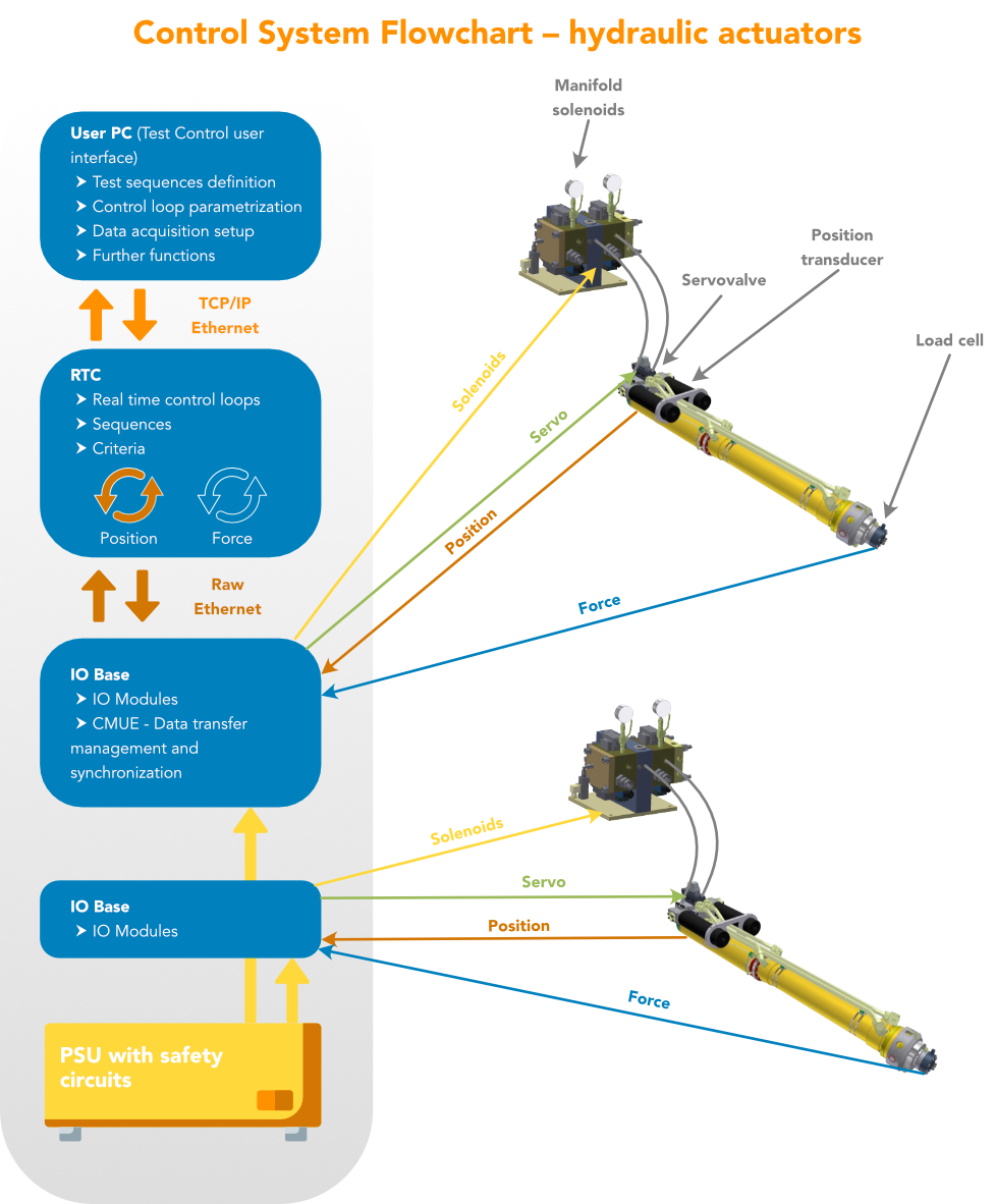
This flowchart illustrates the control system architecture of a hydraulic actuator. The system is divided into five hierarchical levels from top to bottom:
- User PC: Serves as the TestControl user interface for defining test sequences, configuring control loop parameters, and setting up data acquisition. Communicates with RTC via TCP/IP over Ethernet.
- RTC (Real-Time Controller)Executes real-time control loops, sequence control, and criterion evaluation. Supports closed-loop position and force control via Raw Ethernet to the I/O base.
- I/O Base: Includes I/O modules and a CMUE data transmission management and synchronization unit for signal acquisition and distribution.
- On-site EquipmentAccessory components: manifold solenoids, servovalves, position transducers, and load cells for precise hydraulic control.
- PSU with safety circuits: Powers the entire system and ensures safety.
The yellow line represents solenoid control signals, the green line indicates servo control signals, the orange line shows position feedback, and the blue line displays force feedback, forming a complete multi-channel closed-loop control system.
Electric Actuator Control System Overview
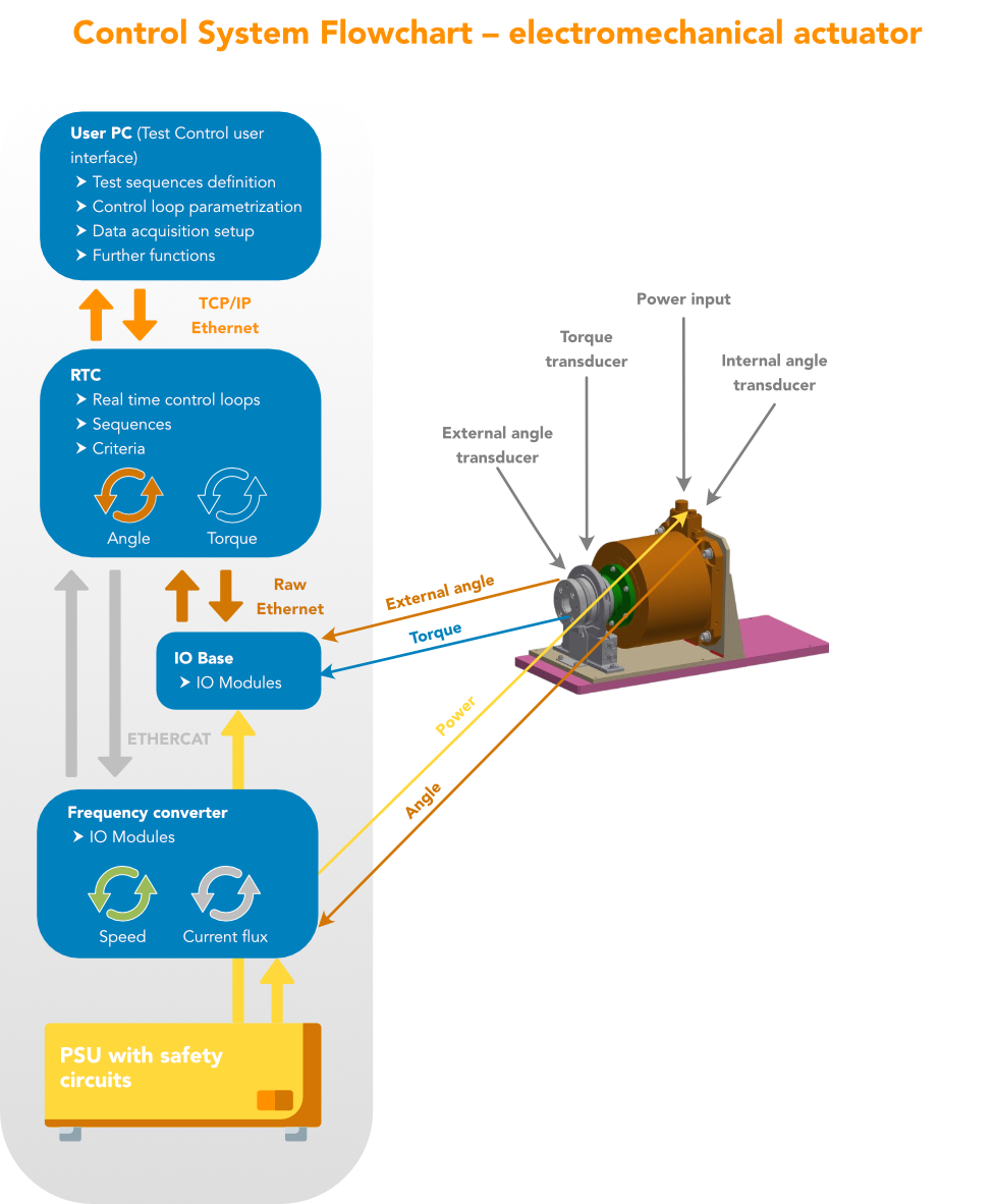
This flowchart illustrates the control system architecture of an electric actuator, which adds a variable frequency drive (VFD) layer compared to hydraulic systems:
- User PC: Provides the same functionality as the hydraulic system, offering a user interface and test configuration.
- RTC (Real-Time Controller): Closed-loop control of angle and torque.
- Frequency Converter: Controls motor speed and current flux; communicates with the upper layer via ETHERCAT.
- Electric actuator: including power input, torque transducer, external angle transducer, and internal angle transducer.
- PSU with safety circuits: Power the system.
The orange line represents the external angle signal (External Angle) and angle control (Angle), the blue line indicates the torque signal (Torque), and the yellow line shows power transmission (Power), enabling precise electromechanical control.
EU3 000 Main Components
User PC
Computer with INOVA TestControl user software installed
Real-Time Communication
Servers with real-time controllers
I/O Foundation
Peripheral Unit (I/O Module) Subrack with transmission paths to two control computer layers
CMUE Communication
Central unit for transmission path, available in a standalone rack module or integrated into an I/O base.
Power Supply Unit (PSU)
Power I/O subsystems, computers, and other devices in the system.
E-Stop Safety Circuit
Integrated into the power unit or as a standalone module
EU3000 System Features
The user PC and RTC use high-reliability components to ensure long-term, stable, and fault-free operation of server-based applications. The user PC includes all standard peripherals for easy operation. The RTC server connects via high-speed Ethernet to I/O cards installed in the INOVA sub-rack. Additionally, the RTC server supports optional communication interfaces—including EtherCAT, FlexRay, CAN, RS-232, RS-485, Modbus RTU, and Modbus TCP/IP—to seamlessly integrate with inverters, PLCs, distributed peripherals, or other devices.
The high-volume data flow between the INOVA I/O base sub-rack and the RTC computer peripheral unit is managed by the transmission system. These components are connected via Synchroblock or CMUE modules in GBE channel frames without transmission speed loss. The data volume transferred between the RTC computer and the user PC over a 1 GB Ethernet interface is significantly lower.
Simulated input and output sampling are fully synchronized, independent of the number of I/O units in the control system, with a maximum actual input/output sampling rate of 50 kHz.
The entire system is powered by a shared power unit. Mains-powered equipment (computers and peripherals) and sub-rack electronics are supplied via UPS backup power. In the event of a mains failure, the backup power automatically engages to ensure safe system shutdown.
The E-Stop subsystem safely halts the system when the operator presses the emergency stop button or a potential hazard is detected. The subsystem and its components are designed to meet Performance Levels c through e (PLc–PLe).
Basic Technical Specifications
| Parameters | Numeric Value |
|---|---|
| Maximum number of sub-racks per subsystem | 8 |
| Max I/O Units per Sub-rack | 15 |
| Max Subsystems per System | 4 |
| Maximum number of control loops per system | 128 |
| Maximum I/O units per system | 480 |
| Distributed Systems — Master-Slave Distance | Up to 50 m |
| Simulate Input Resolution | 24 |
| Simulated Output Resolution | 16 |
| Maximum Sampling Frequency | 50 kHz |
| 10 kHz order channel rate limit | No |
| Maximum Independent Trials | 12 |
Operating and Environmental Conditions
Complies with Section 4.4 of CSN EN 60204-1:
- Electromagnetic compatibility (EMC) meets the requirements of Section 4.4.2.
- Relative humidity: maximum 50% (at +28°C), 90% (at +20°C), as required in Section 4.4.4.
- Ambient temperature +10°C to +28°C, optional +35°C
Software
The INOVA test stand includes the TestControl software suite, a proprietary graphical user interface with advanced features for a wide range of testing applications. TestControl communicates with RTC server computers connected directly to I/O units, providing full control over the connected hardware. Additionally, TestControl displays and processes data from the RTC computer and offers operators powerful capabilities, including creating user-defined control loops, defining load sequences, data acquisition, real-time mathematical operations on measurement signals (e.g., digital filtering, linearization), post-processing, analysis and evaluation, and calibration management.
EU3000 Model
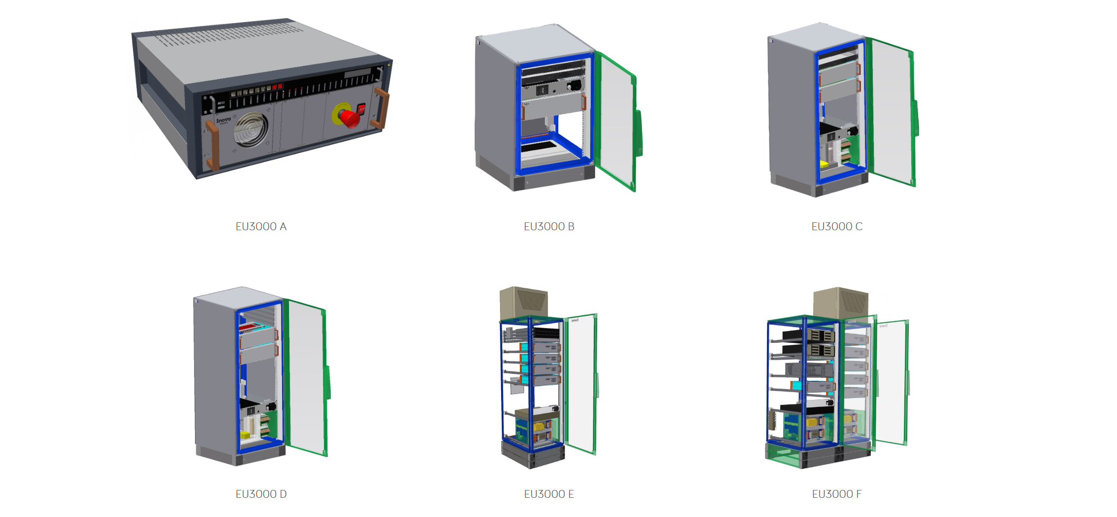
The EU3000 is available in multiple versions that differ in rack dimensions, maximum number of connectable I/O modules to the system (with any combination of module types), 24 VDC maximum output current, and maximum control loop count. Small systems use a compact chassis that includes the power supply, space for 8 peripheral units, and an emergency stop subsystem.